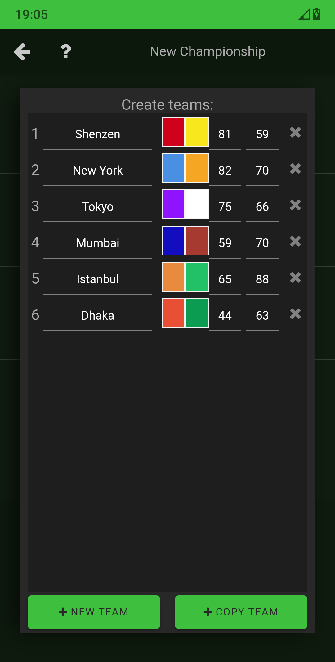
Android app
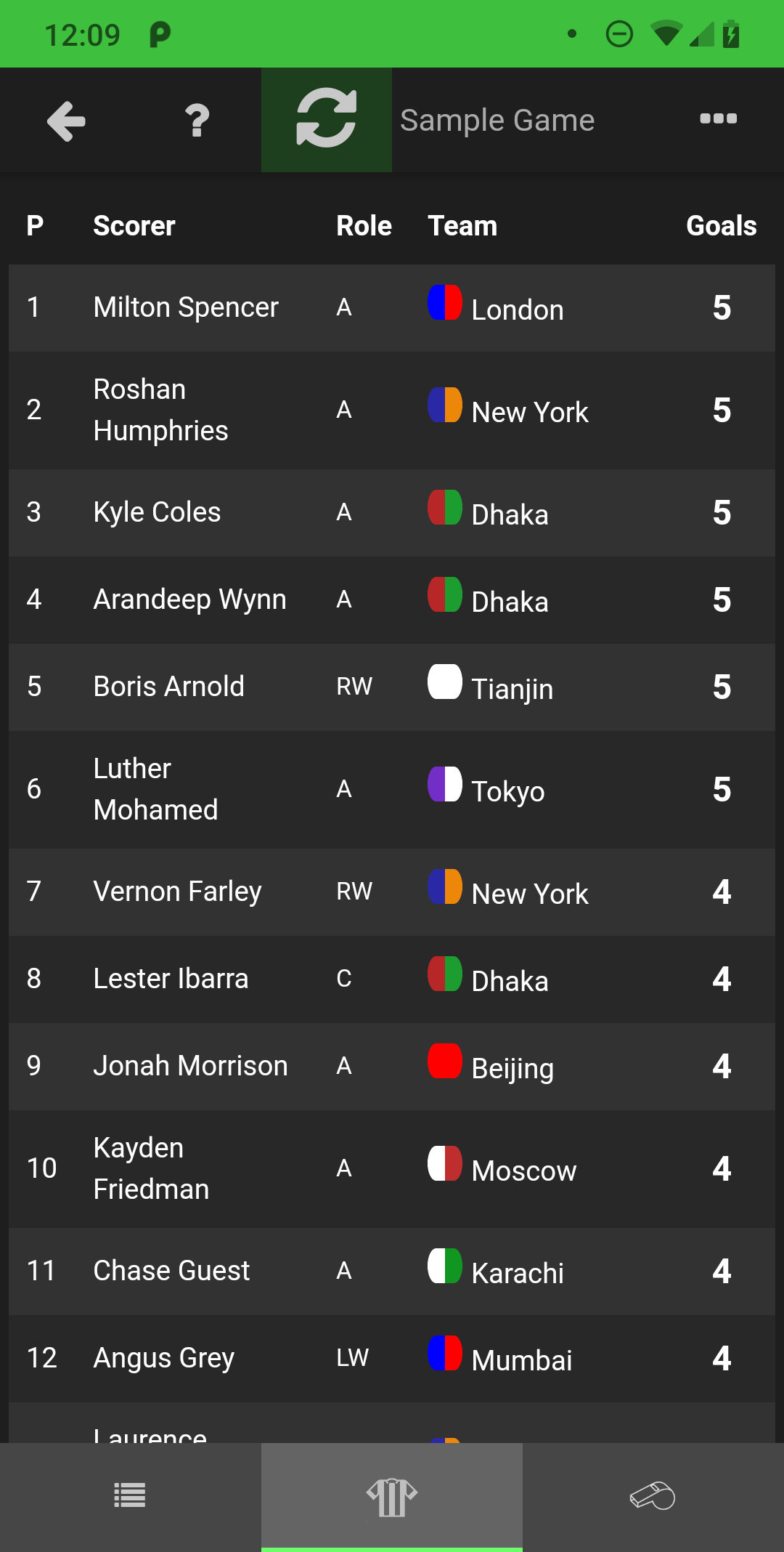
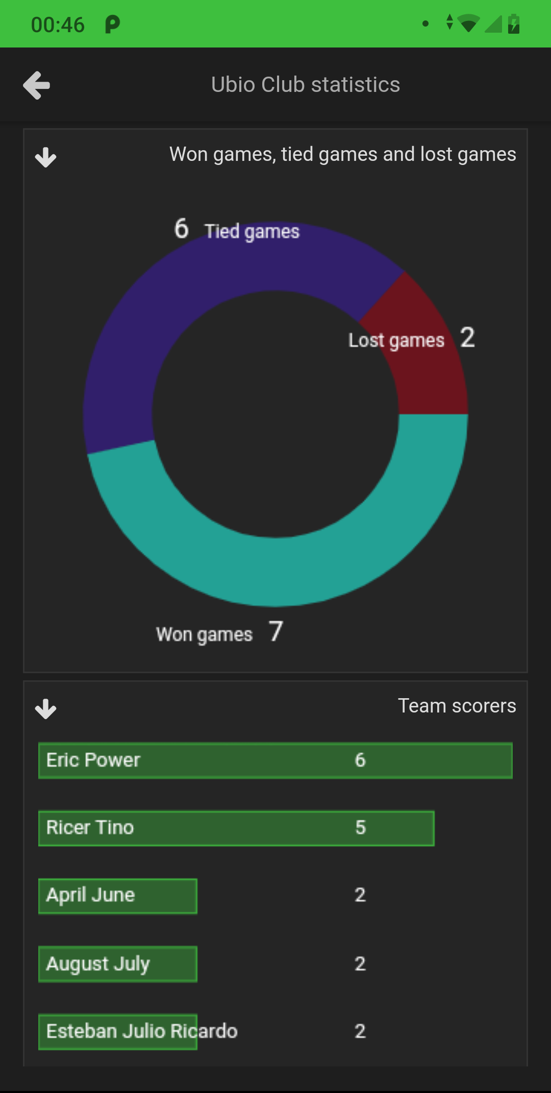
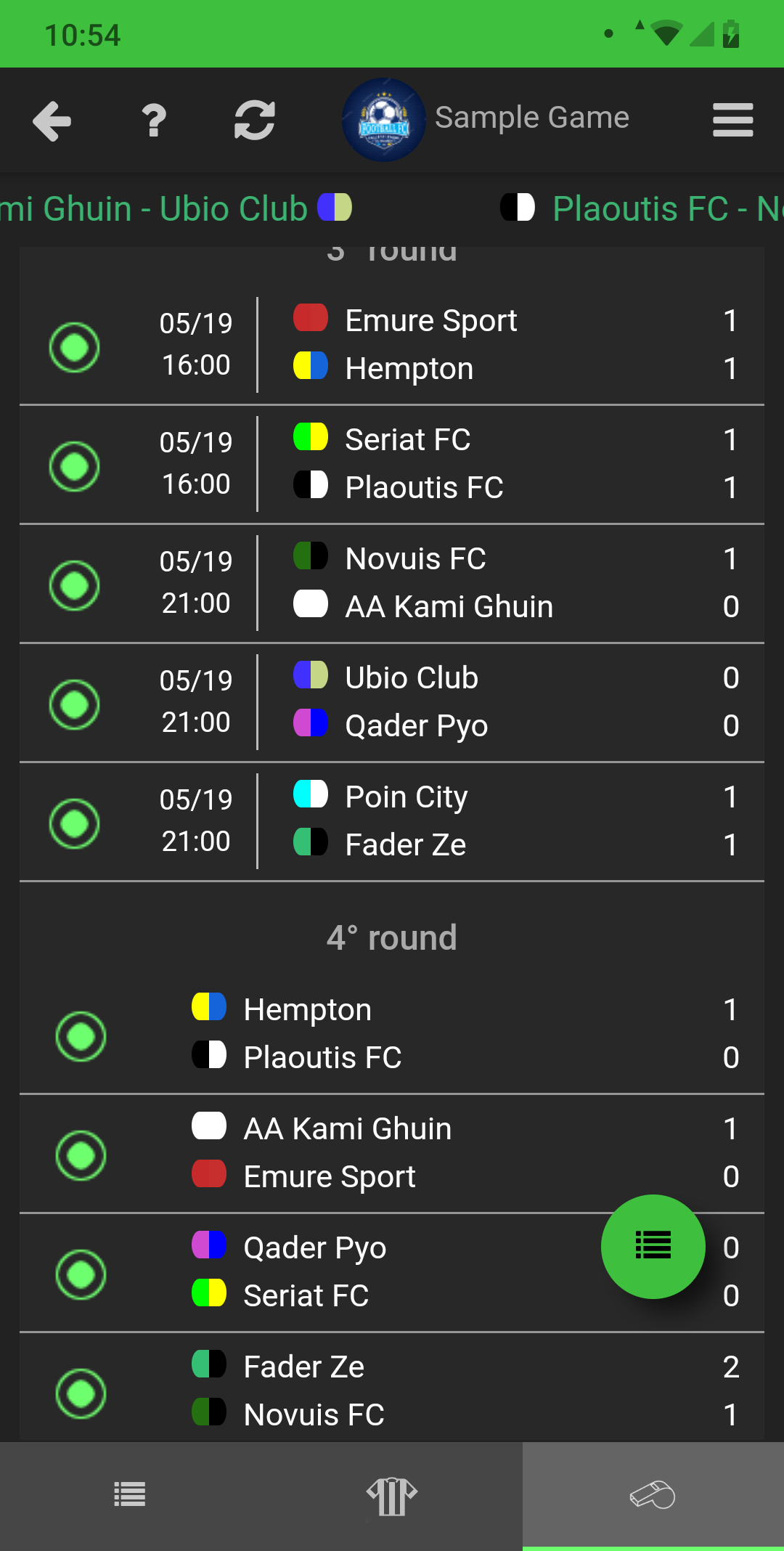
Android application screenshots

: The RTC crystal must oscillate to provide timing for the Southbridge's standby logic.
: The CMOS battery provides voltage to the Southbridge/PCH to maintain the Real-Time Clock (RTC).
Before the power button is even pressed, the motherboard must establish baseline voltages to listen for a wake signal.
The is a highly structured, step-by-step process that ensures all components—from the chipset to the CPU—receive stable power in the correct order to prevent hardware damage and ensure a successful boot. Understanding this sequence is essential for diagnosing "no power" or "no display" issues. Core Stages of the Power Sequence
: The SIO sends this 3.3V high-level signal to the PCH to notify it that standby power is stable and the system is ready to be "resumed". 2. Triggering Phase (Power Button Event)
This phase initiates the transition from a "Soft Off" (S5) state toward full operation. Desktop Motherboard Power Sequence Explained - Scribd
: When the ATX power supply is plugged in, it immediately sends +5V standby (purple wire) to the Super I/O (SIO) chip.
The power-on process moves through several distinct states, often following ACPI standards from to S0 (Working State) . 1. Pre-Trigger / Standby Phase (G3 to S5)
: The RTC crystal must oscillate to provide timing for the Southbridge's standby logic.
: The CMOS battery provides voltage to the Southbridge/PCH to maintain the Real-Time Clock (RTC).
Before the power button is even pressed, the motherboard must establish baseline voltages to listen for a wake signal. desktop motherboard power sequence pdf exclusive
The is a highly structured, step-by-step process that ensures all components—from the chipset to the CPU—receive stable power in the correct order to prevent hardware damage and ensure a successful boot. Understanding this sequence is essential for diagnosing "no power" or "no display" issues. Core Stages of the Power Sequence
: The SIO sends this 3.3V high-level signal to the PCH to notify it that standby power is stable and the system is ready to be "resumed". 2. Triggering Phase (Power Button Event) : The RTC crystal must oscillate to provide
This phase initiates the transition from a "Soft Off" (S5) state toward full operation. Desktop Motherboard Power Sequence Explained - Scribd
: When the ATX power supply is plugged in, it immediately sends +5V standby (purple wire) to the Super I/O (SIO) chip. The is a highly structured, step-by-step process that
The power-on process moves through several distinct states, often following ACPI standards from to S0 (Working State) . 1. Pre-Trigger / Standby Phase (G3 to S5)
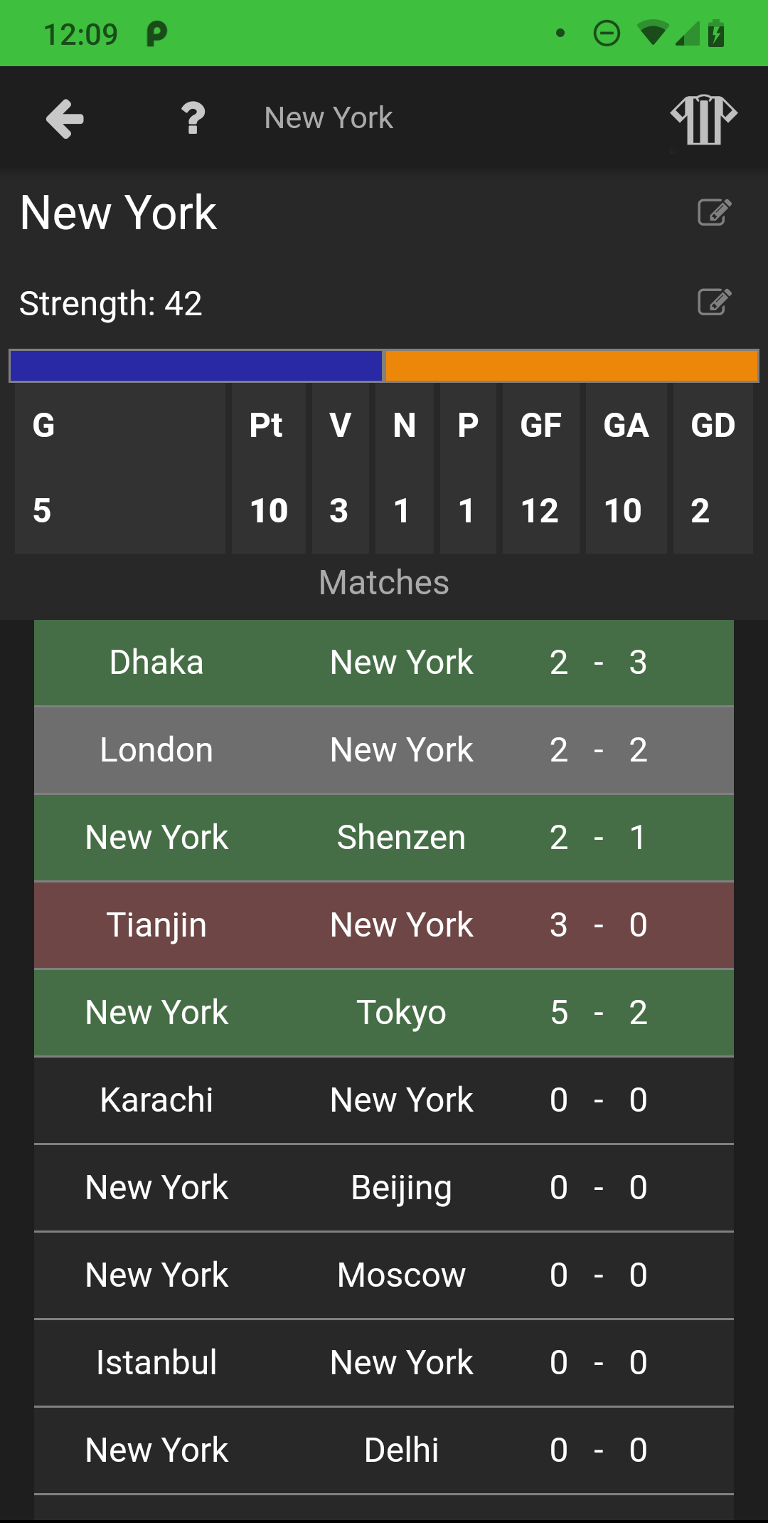
Android application screenshots